Building the hardware for a room sensor
Here at Cranfield University we are putting in place plans related to the new ‘Living Laboratory’ project, part of our ‘Urban Observatory’. This project sits within the wider UKCRIC initiative, across a number of universities. Of the many experiments in development, we are gathering environmental data from IoT devices and building data dashboards to show the data and related analyses. One of our projects will be to investigate air quality on the campus, in our lecture rooms and public spaces. Cranfield is a unique University in the UK for having its own airfield as part of the campus – we want to monitor any particular impacts that can arise from this. In this blog we discuss building the hardware for a room sensor to detect levels for temperature, humidity, barometric pressure and VOC (volatile organic compounds).
In previous blogs, we have explored the use of the fantastic Bosch BME680 sensor from PiMoroni with the equally fantastic Particle Photon board to detect environmental characteristics. This blog post is more about building the hardware for the sensor, describing a prototype design.
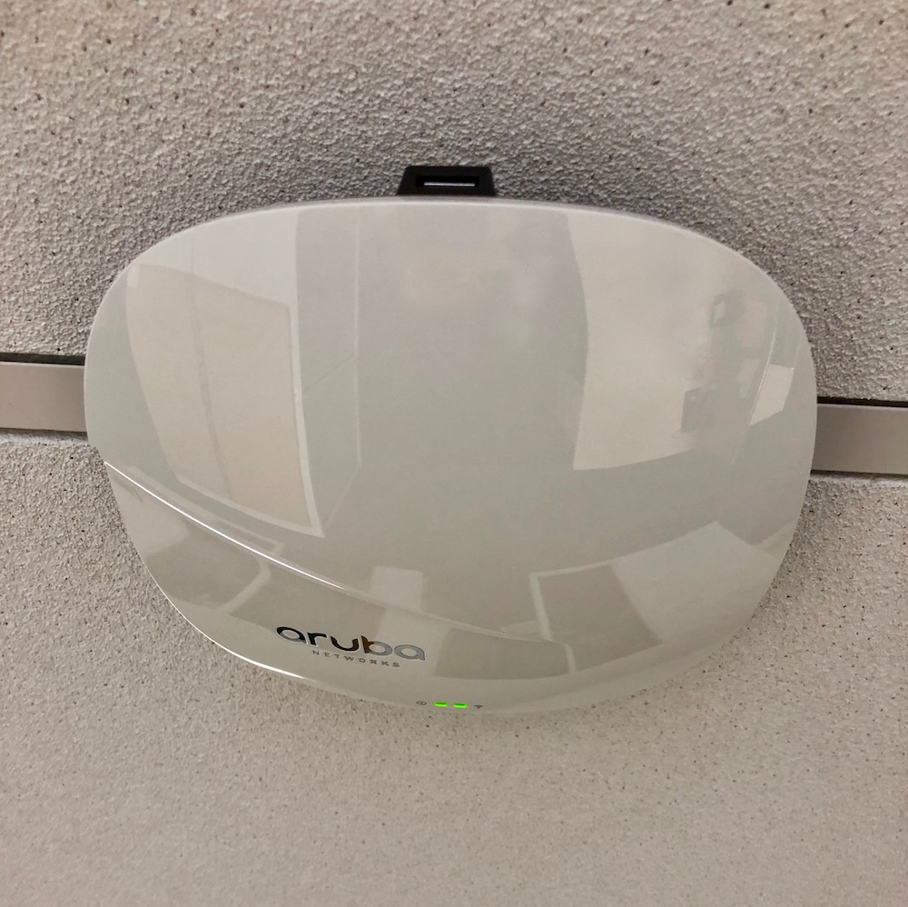
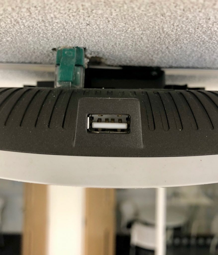
An initial issue is how to site the sensor in a room. We were considering at first fixing sensors to walls, and running power to the case with trunking going up the wall from power sockets. This is all pretty unsightly and obtrusive. However, an idea then emerged that offers a perfect solution. Each room has a WiFi router positioned centrally on the ceiling, and each router has a spare USB socket. The design goal was therefore to design a plug-in unit that can be positioned in this USB socket. There certainly shouldn’t be an issue with WiFi connectivity!
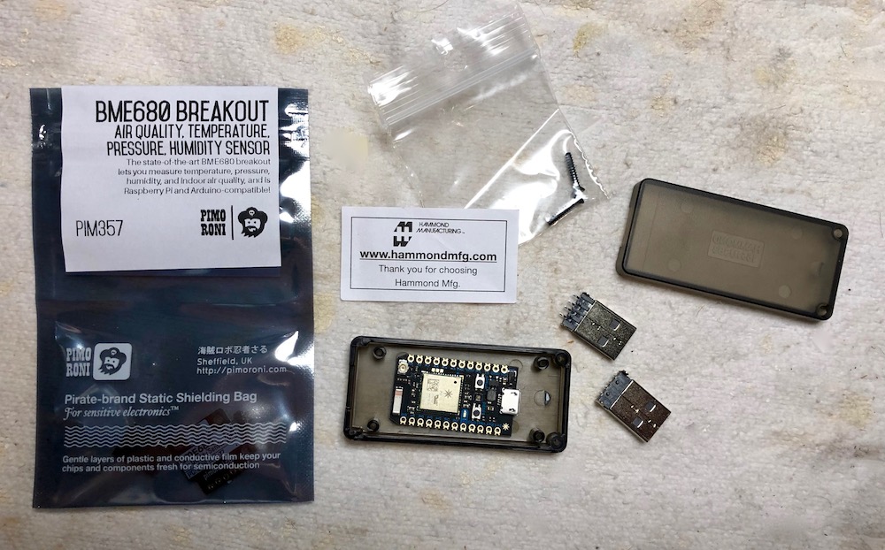
We therefore looked to find a suitable case to fit a Particle photon, and the sensor, with the ability to plug into the USB socket. We found the perfect case from Farnell, the Hammond 1551USB3TSK USB Plastic Enclosure. We also bought a right angled USB PCB plug. Together with the Photon and BME680, all the parts looked like this.
The next stage involved soldering the PCB USB connector onto a piece of veroboard and cutting it to fit with the trusty Dremmel saw, drill and deburring tool.
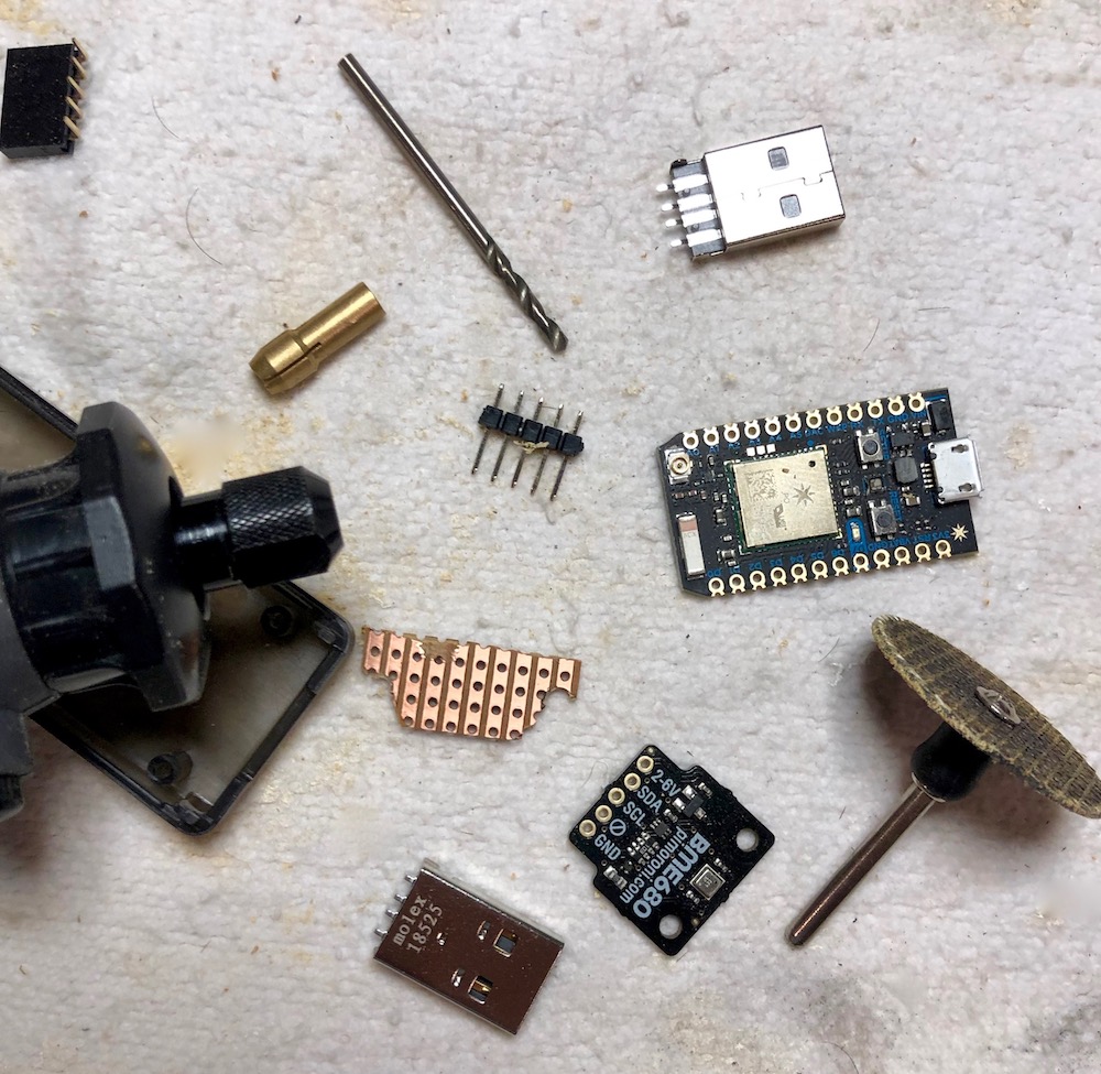
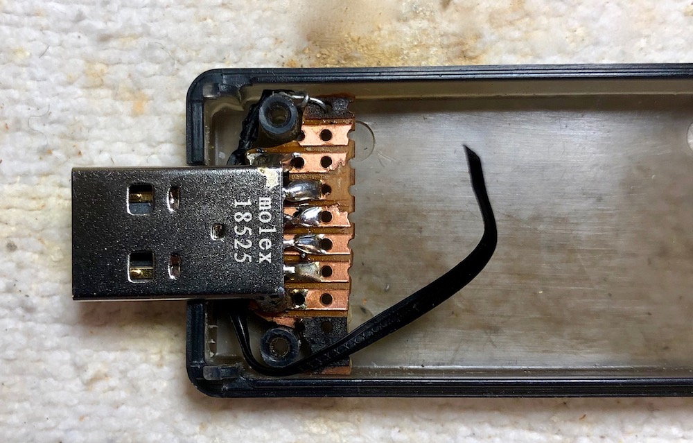
After much fiddling with the components, the piece was starting to take shape. The first task was to fit the USB connector. We cut out a piece of veroboard and then cut it to fit. As can be seen this was a pretty fiddly task. The USB plug needed fixing in place so the case could plugged in and removed without the USB plugboard moving. Next time we realised we should use the case pillars better and cut a slot out to fit around them!
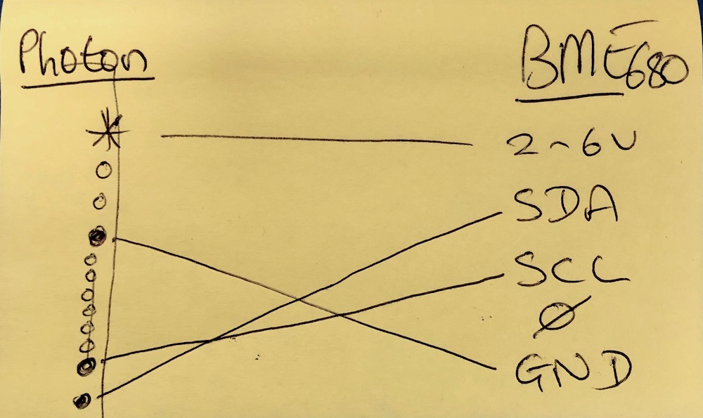
Finally, after the USB board was fitted, the rest of the components could be fitted and wired up. The other end of the case then had a small slot routed in to allow the sensor to be stuck through to poke outside. We found that in use the Photon can heat up, so we wanted the temperature sensor located as far away as possible from it and to have the sensor exposed to the air. We then needed to wire the components up permanently which meant soldering wires in rather than using the header pillars that our earlier prototype had used. We had our wiring diagram to work to from our prototype.
We realised there was not enough space in the case for adding header blocks on the Photon or the sensor, so soldering directly to their PCBs was the only way to proceed. Soldering makes a permanent join, but the electronics of both the photon and BME680 sensor are very delicate, so we were careful to use the absolute minimum heating time from the soldering iron to make the joins, and use a solder with plenty of flux. This resulted in satisfactory joins. Also, we needed to get the 5v power to the Photon from the USB plug unit. To to this we took the power lines off and soldered directly to the VIn and Gnd pins on the photon (bypassing the micro USB socket).

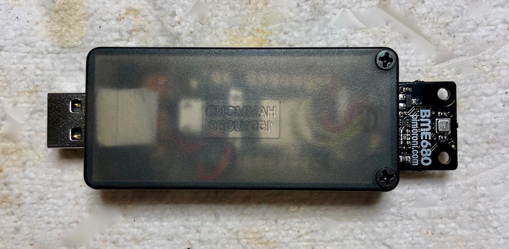
Once the wiring was all in place and all the solder joints checked carefully under a powerful magnifying lens (to check there were no ‘dry’ joints), the components could be packed out with sticky pads to ensure there was no rattling around. Finally we could fit the lid on the case and screw it all into place.

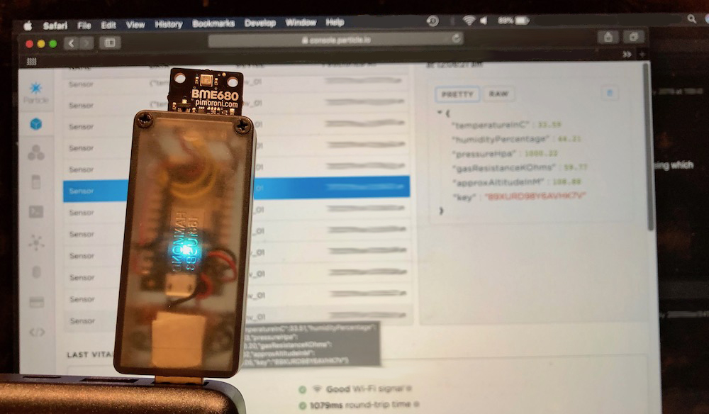
The final assembly was very satisfactory. We could turn it on to test it by plugging it into a USB charger battery. The photon was brand new and so commenced the setup routine with the flashing blue light. We were able to then connect to it with our mobile, claim and name the deice, and then upload the source code previously written. able to save off a JSON structure with all the data included to the Particle cloud on a regular basis. The Photon’s excellent design means that even once one or more units are deployed, their code can be flashed remotely to update their functionality. Multiple devices can be grouped into ‘products’ to allow concurrent code maintenance. We realise we will have to work out how to have photons automatically identify themselves individually when multiple data sources are collated to one database – something to think about next!
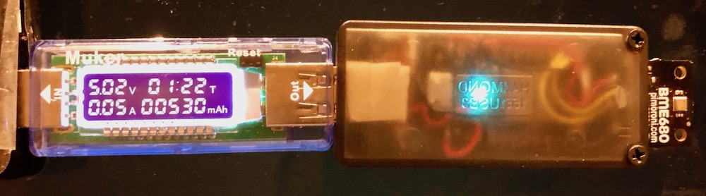
A test of the electrical current for the completed unit shows a draw of about 530mAh, which is pretty small for such a sensor and acceptable in that it isn’t drawing off too much current.
Epilogue
The exercise here is more one of hardware than of software – all the code and software methodologies were sorted as described with the earlier prototype. Here we have a physical design which will do what we want, plugging unobtrusively into a spare USB socket located on a WiFi router on the ceiling. The device will be now fixed into place in a lecture room and tested. To extend the project to a campus-wide solution, ideally a custom PCB would be created, designed to fit the case perfectly (or a dedicated case could be designed and 3D printed). Also, to gather the data together, potentially from multiple sources we will need a ‘dashboard’ and a linked database in a system able to receive the data streams. This solution would be bigger than the ThingSpeak tooling we have used for recent prototypes. We have been experimenting with ThingsBoard for this system scale solution, with a provisional version already running on a test Raspberry Pi – perhaps this will become the subject for a future blog.
]]>