


In this blog we will describe the steps needed to do some machine vision using the Raspberry Pi Zeros we described in the earlier blog. Here at Cranfield University we are building these amazing devices into our research. In this case we are interested in using the Pi as a device for counting pedestrians passing a site – trying to understand how different design choices influence people’s choice of walking routes.
Contents:
Background
Toolkits
Kerberos
Installation of Kerberos
Configuration of Kerberos
Configuration of the Pi
Output and Data Capture from Kerberos
Epilogue
Background:
top
In the earlier blog we showed how to set up the Raspberry Pi Zero W, connecting up the new v2 camera in a case and connecting power. Once we had installed Rasbian on a new microSD card all was ready to go.
A bit of research was needed to understand the various options for machine vision on a Pi. There are three levels we might want. First a simple motion detection with the camera would give a presence or absence of activity, but not much more. This could be useful when pointing the camera directly at a location. Second, we can use more sophisticated approaches to consider detecting movement passing across the camera’s view, for example left to right or vice versa. This could be useful when pointing the camera transverse to a route along which pedestrians are travelling. Thirdly, and with the ultimate sophistication, we could try and classify the image to detect what the ‘objects’ passing across the view are. Classifier models might for example detect adults, young persons, and other items such as bicycles and push buggies etc. Needless to say, we wanted to start off easy and then work up the list!
Looking at the various software tools available, it is clear that many solutions draw on OpenCV (Open Source Computer Vision Library) (https://opencv.org). OpenCV is an open source computer vision and machine learning software library, built to provide a common infrastructure for computer vision applications and to accelerate the use of machine perception. There are many other potential libraries for machine vision – for example, SOD (https://sod.pixlab.io), and other libraries such as Dlib (http://dlib.net). OpenCV can be daunting, and there are wrappers such as SimpleCV (http://simplecv.org) to try and simplify the process.
Toolkits:
top
We then looked at options for toolkits that use these basic building blocks. A useful reference is Jason Antman’s blog here https://blog.jasonantman.com/2018/05/linux-surveillance-camera-software-evaluation/. Although not Jason’s final choice, the tool that stuck out to us was Kerberos (https://kerberos.io), developed by Cedric Verstraeten and grown out of his earlier OpenCV project (https://github.com/cedricve/motion-detection).
Kerberos:
top
 Kerberos has a number of key resources:
Main home website – https://kerberos.io
Documentation – https://doc.kerberos.io
Git – https://github.com/kerberos-io
Helpdesk – https://kerberosio.zendesk.com
Corporate – https://verstraeten.io
Gitter – https://gitter.im/kerberos-io/home
Although the full source for Kerberos is available, and also a docker implementation, what we really liked was the SD image for the Raspberry Pi Zero – so really made for the job.
Installation of Kerberos:
top
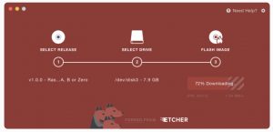
We downloaded the cross-platform installer from the Kerberos website. This is based on the Etcher tool, used to install Rasbian so familiar to any Pi user. In our case we selected the Mac installer, downloading an installer dmg file (c.80Mb). Then, ensuring the Micro SD card destined for the Pi was in a flash writer dongle attached to the Mac, we were able to easily install the image. The Etcher app asks a couple of questions on the way about the WiFi network SSID and WiFi and system passcodes, as well as a name for the device, and writes these details onto the SD card with the rest of the image. As a result, on inserting the SD card and booting the Pi with the Kerberos image, the device started up and connected correctly and without issue on the WiFi network. A check on the router on our closed network showed the device had correctly registered itself at IP address 192.168.1.24.
Management of the Pi and camera is achieved via app running on a web server on the Pi. So to access our device, we entered browsed the URL http://192.168.1.24/login.
Configuration of Kerberos:
top
The dashboard app provides complete control over the operation of the Pi and camera.The image here shows the ‘heatmap’ camera view, and statistical graphs and charts of timings of activations.
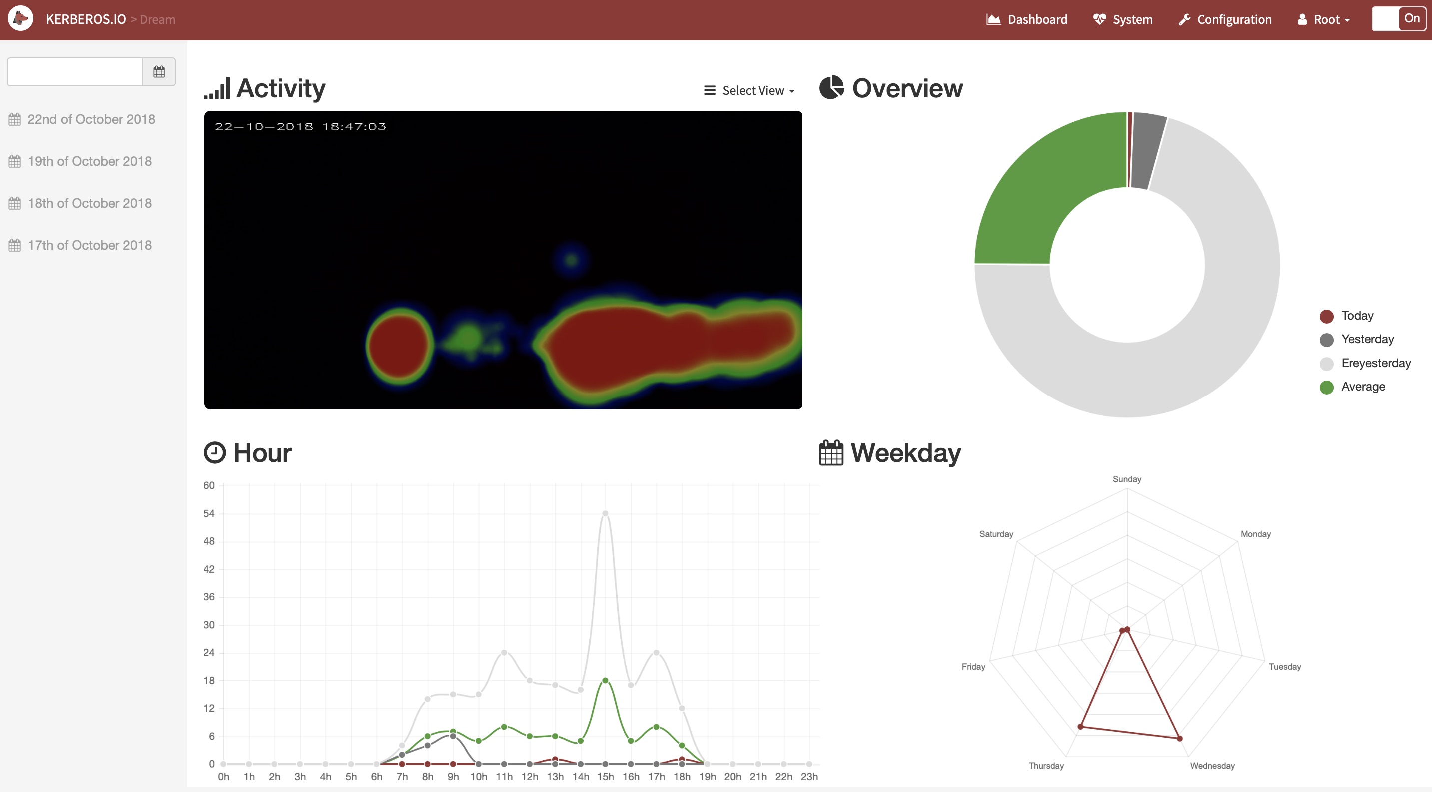 . To configure the many settings we headed over to https://doc.kerberos.io for the documentation. The concept is that the image processing is undertaken on the ‘Machinery’ configuration, and that the ‘Web’ then controls access to the results.
Selecting ‘Configuration’ we could start adjusting the settings for the Machinery as we required. There are default settings for all the options.
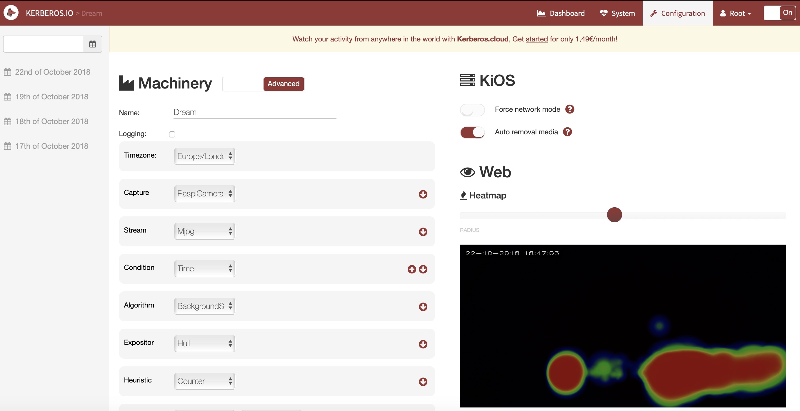 However, the settings you will use depend on the application for the device. We followed the settings for ‘People Counter‘ recommended both in the docs, and a subsequent blog. It seems that there the settings are very sensitive, so one has to adjust until the desired results are obtained.
Being on a Raspberry Pi, one can also ssh connect directly to the device on a terminal connection (eg from terminal on the Mac, or via Putty from a PC). Connect to the device with the command:
ssh root@192.168.1.22
cd /data/machinery/config
This takes you to the location of the configuration files, as written out by the web app. Below are the settings we used to get the People Counter working (the values here correspond to the settings in the web app).
less config.xmlStationery false Europe-London RaspiCamera Mjpg Enabled DifferentialCollins Rectangle Counter Webhook S3
less capture.xmlxxxxxxxxx 640 480 500 0 640 480 0 MJPG 500 0 640 480 500 0 20 0 0 0 50 640 480 0 500 0
less stream.xmltrue 8889 75 15
less condition.xmltrue 5000
less algorithm.xml5 15 false 15 5 1 5 7 10
less expositor.xml0 0 800 600 779,588|781,28|588,48|377,31|193,31|32 ,45|33,625|191,591|347,600|456,572|556,601|659,629
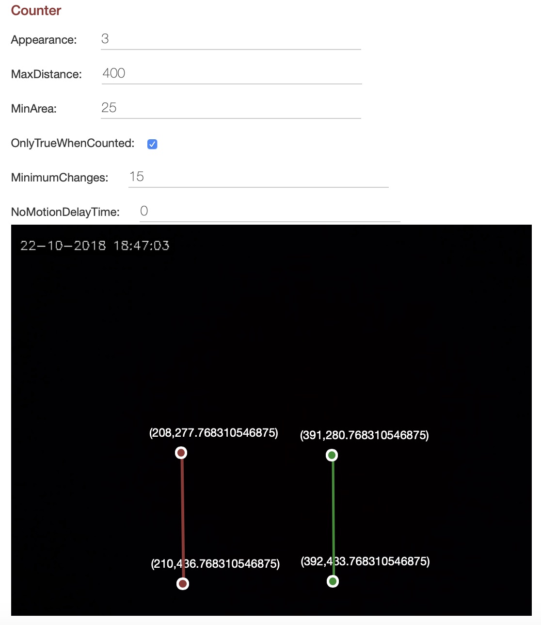
less heuristic.xml20 2 1000 3 140 200 false 5 100 34,29|36,461|617,22|614,461
Note the settings above for the twolines markers on the video image – used for counting pedestrians passing from left to right, and from right to left, (coordinate position 0,0 is the top left corner)
less io.xmltimestamp_microseconds_instanceName_regionCoord inates_numberOfChanges_token.jpg /etc/opt/kerberosio/capture/ false white false 0 17 1 100000 0 IP_ADDRESS:3000/counter motion-detected 0 IP_ADDRESS:3000/counter 500 false false IP_ADDRESS 1883 kios/mqtt 0 https://api.pushbullet.com xxxxxx 10
Configuration of the Pi:
top
Another configuration required was to tun off the bright green LED on the Raspberry Pi as it draws attention when the unit is operating. To turn OFF the LEDs for Zero, we followed the instructions at https://www.jeffgeerling.com/blogs/jeff-geerling/controlling-pwr-act-leds-
raspberry-pi. Note that unlike other Raspberry Pi models, the Raspberry Pi Zero only has one LED, led0 (labeled ‘ACT’ on the board). The LED defaults to on (brightness 0), and turns off (brightness 1) to indicate disk activity.
To turn off the LEDs interactively, the following commands can be run each time the Pi boots.
# Set the Pi Zero ACT LED trigger to 'none'.
echo none | sudo tee /sys/class/leds/led0/trigger
# Turn off the Pi Zero ACT LED.
echo 1 | sudo tee /sys/class/leds/led0/brightness
To make these settings permanent, add the following lines to the Pi’s ‘/boot/config.txt’ file and reboot:
# Disable the ACT LED on the Pi Zero.
dtparam=act_led_trigger=none
dtparam=act_led_activelow=on
Note the ‘/’filesystem is made read-only by default in the Kerberos build. To temporarily fix this to force read write for the root ‘/’ filesystem, type:
mount -o remount,rw /
Now the config.txt file can be edited normally, e.g. in the editor nano, and then the Pi can be rebooted.
cd /boot
nano config.txt
reboot
Output and Data Capture from Kerberos:
top
To obtain data from the tool, we are using the ‘script’ setting in io.xml, which runs the script ‘/data/run.sh’ (a bash script). This script just writes the data receives (a JSON structure) out to disk.
#!/bin/bash

# -------------------------------------------
# This is an example script which illustrates
# how to use the Script IO device.
#

# --------------------------------------
# The first parameter is the JSON object
#
# e.g. {"regionCoordinates":[308,250,346,329],"numberOfChanges":194,"timestamp":"1486049622","microseconds":"6-161868","token":344,"pathToImage":"1486049622_6-161868_frontdoor_308-250-346-329_194_344.jpg","instanceName":"frontdoor"}

JSON=$1

# -------------------------------------------
# You can use python to parse the JSON object
# and get the required fields

echo $JSON >> /data/capture_data.json

coordinates=$(echo $JSON | python -c "import sys, json; print json.load(sys.stdin)['regionCoordinates']")
changes=$(echo $JSON | python -c "import sys, json; print json.load(sys.stdin)['numberOfChanges']")
incoming=$(echo $JSON | python -c "import sys, json; print json.load(sys.stdin)['incoming']")
outgoing=$(echo $JSON | python -c "import sys, json; print json.load(sys.stdin)['outgoing']")
time=$(echo $JSON | python -c "import sys, json; print json.load(sys.stdin)['timestamp']")
microseconds=$(echo $JSON | python -c "import sys, json; print json.load(sys.stdin)['microseconds']")
token=$(echo $JSON | python -c "import sys, json; print json.load(sys.stdin)['token']")
instancename=$(echo $JSON | python -c "import sys, json; print json.load(sys.stdin)['instanceName']")

printf "%(%m/%d/%Y %T)T\t%d\t%d\t%d\t%d\n" "$time" "$time" "$changes" "$incoming" "$outgoing" >> /data/results.txt
Note the use of the parameters to convert the Julian timestamp to a readable date/time.
When an event triggers the system (someone walking past the camera view) two actions follow, an image is saved to disk, and the script is run, with a parameter of the JSON structure. The script then processes the JSON. The script here both writes out the whole JSON structure to a the file ‘capture_data.json’ (this is included as a debug and could be omitted), and also extracts out the data elements we actually wanted and writes these to a CSV file called ‘results.txt’.
A sample of ‘capture_data.json’ look like this:
{"regionCoordinates":[413,323,617,406],"numberOfChanges":1496,"incoming":1,"outgoing":0,"name":"Dream","timestamp":"1539760397","microseconds":"6-928567","token":722,"instanceName":"Dream"}
{"regionCoordinates":[190,318,636,398],"numberOfChanges":2349,"incoming":1,"outgoing":0,"name":"Dream","timestamp":"1539760405","microseconds":"6-747074","token":814,"instanceName":"Dream"}
{"regionCoordinates":[185,315,279,436],"numberOfChanges":1793,"incoming":0,"outgoing":1,"name":"Dream","timestamp":"1539760569","microseconds":"6-674179","token":386,"instanceName":"Dream"}
A sample of ‘results.txt’ looks like this:
10/17/2018 08:17:08	1539760628	917	0	1
10/17/2018 08:17:18	1539760638	690	0	1
10/17/2018 08:18:56	1539760736	2937	0	1
10/17/2018 08:19:38	1539760778	3625	1	0
10/17/2018 08:22:05	1539760925	1066	1	0
10/17/2018 08:24:06	1539761046	2743	0	1
10/17/2018 08:24:45	1539761085	1043	1	0
10/17/2018 08:26:11	1539761171	322	0	1
Epilogue:
top
This blog has shown how the Kerberos toolkit has been used with an inexpensive Raspberry Pi for detecting motion and also directional movement across the camera view. The data captures a JSON data structure for each event triggered, and a script extracts from this the data required, which is saved off to disk for later use.
There are still issues to grapple with – for example reduce false positives, and perhaps more importantly not missing events as they occur. The settings of the configuration machinery are very sensitive. The best approach is to successively vary these settings (particularly the expositor and heuristic settings) until the right result is obtained. Kerberos has a verbose setting for event logging, and inspecting the log with this switched on reveals that the Counter conditions are very sensitive – so many more people may be walking past the camera than are being directly logged as such (e.g. motion activations may be greater than count events).
The commands below show how to access the log – it is also shown in the ‘System’ tab of the web dashboard. The command ‘tail -f’ is useful as it shows the log update in real time – helpful if the video live feed screen is being displayed alongside on-screen. Then you can see what is and isn’t being logged very easily.
cd /data/machinery/logs
tail -f log.stash
Ultimately, the Raspberry Pi may not have enough power to operate full classifier models, such as that developed by Joseph Redmon with the Darkweb YOLO tool he developed (‘You Only Look Once’) (https://pjreddie.com/darknet/yolo/). However, Kerberos itself has a cloud model that provides post-processing of images in the cloud on AWS servers, with classifier models available – perhaps something to try in a later blog.
]]>